A Secure and Reliable Stack Protocol for Embedded Sensor Nodes
Introduction
The project presented this year from the students of the Embedded Systems course at University “Federico II” of Neaples, shows a sensors network realized with STM32F4 boards, using a reliable and secure stack protocol.
The aim of this project is to obtain a network that can communicate in a “secure and reliable” way: to do that, we created protocol layers with all the features that could give us a simple and risolutive solution.
2 Application layer
This layer coexists in all sensors, made by two entities:
- Sensor Node;
- Control Center.
Data and control frames are sent from sensors to control center, in order to give it information about physical and configuration data; the center receives these frames, making some elaborations and storing them in a non-relational database, MongoDB.
2.1 Sensor Node
This node has to manage sensors both on-board and out-board, allowing them to comunicate on the network; the management of the sensors is done with an API called GSI (Generic Sensor Interface)
- GSI provides an abstraction of the physical details of the sensors, giving functionalities for sensors’ initialization and data reading.
2.1.1 Packet format
The packet managed by the Sensor node is composed by :
- a code, an identifier for the type of the packet;
- the payload, a data structure that hold the following information:
- ID : each sensor node has a unique ID;
- period : in ms, represents the period used by the node to send sensors' data. If the value in this field is 0, the sensor is questioned in asynchronous mode.
- priority : the priority of the sensor node.
- threshold : data structure that contains the normal thresholds (high and low) to detect anomaly in the behaviour of the sensor.
- alarm : identifies an alarm in the packet.
2.2 Control Center
Physically, the Control Center is made by two devices:
- a general-purpose calculator, used for DB and data presentation;
- the software architecture is layered, implemented by the MVC pattern:
- Model is made by a non-relational DB, using the MongoDB techonology;
- Controller is implemented by a server (Node.js);
- View is made by a Angular.js client.
- the entire stack uses JavaScript.
- the software architecture is layered, implemented by the MVC pattern:
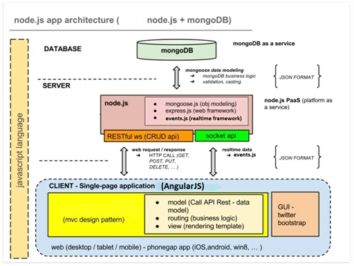
- a STM32F4 board, that represents the Center Node for the network, and bridge for all communications between Sensors and PC
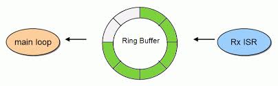
- The implemented communication is secure, so the Central Node makes some elaboration to verify that the packets received by the network are compliant with the security protocols.
- In order to make a good managment of these packets, the receiving queue is implemented as a ring buffer, ensuring a interrupt-safe behaviour.
- The implemented communication is secure, so the Central Node makes some elaboration to verify that the packets received by the network are compliant with the security protocols.
2.2.1 Server component
The functionalities of this component are:
- connection with the DB;
- communication APIs with the clients (RESTful webservice);
- managment of real-time communication using WebSocket.
In particular, Node.js is a software platform based on Chrome’s V8 JavaScript Engine, that uses a I/O model event-oriented, making it useful for real-time applications.
Additional modules of this component are:
- mongodb : for the management of the connection between Node.js and MongoDB
- mongoose : for the modeling of the stored data in DB
- this module makes the data typing, but also the business logic of the application.
- express : for the web application
- bcrypt : for the encryption of the password between Control Center and Sensors.
2.2.2 Client/Server communication component
Client uses the REST APIs to communicate with the server, which define the available services.
The funcionalities exposed use the HTTP protocol.
2.2.3 Client component
The client side of the application requests information from server, then they are displayed. Grafic components are managed by HTML, there are three web pages:
- a dinamic page for displaying the monitored data;
- a page for the admin login;
- a page of network managment.
3 Security layer
The security requirements of the network are:
- Confidentiality : the data sent from the sensors has to be red only from the control center, and viceversa;
- Authentication : the receiver of a message in the network must be sure that the sender is really who it claims;
- Integrity : the messages can be altered.
The presented solution is compliant with these concepts, and balances tradeoff between economic costs, performance and power consumption.
After drafting a model attacker, we made some recruitments to simplify the project and exclude event with low probability:
- Control center is not accessible : with this hypothesis we exclude the tampering of a very important node in our network;
- On board flash memory is secure : with this hypothesis we exclude the tampering attack to the flash memory of the nodes, that is used to store a simmetric key, as we see in the following sections.
3.1 Security protocols
Based on the arguments discussed and on the attacker model, we implemented a security protocol that can make secure the sensor network in all its lyfe cycle.
- Initialition phase
- The nodes in the network are physically connected to the control node to receive a simmetric key. We choose a simmetric mechanism to improve performance and power consumption;
- The control node stores a ket for any operative node;
- The key is stored from the nodes in their flash memory, so they can be transported without any problem;
- The encryption algorithm is AES-128, that gives good performance and it’s strong against Bruteforce attacks; however, this mechanism can be changed, setting the nodes and the keys.
- The nodes that has got a key is inserted in a Whitelist: it contains the node’s ID, its key, and a field that contains ack.
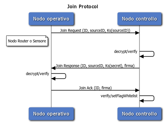
- Join phase
- Each node requests to the central node a secret, that it’s use to sign the messages with HMAC using MD5. This secret is the same for each node: this mechanisms is useful to avoid an eccessive storage for the control center, and to permit to verify the signature to all the sensors in the network.
- The secret is generated by the central node using the TRNG (True Random Number Generator) present on the board.
- The secret exchange is done by a three-way handshake, using specified frames that assure that this one has been done in a good and secure manner:
- The node that want to receive the secret, send a JOIN REQUEST frame, that contains its unique ID and another field in which it encrypt its ID with the symmetric key obtained by the central node;
- The central node receive the Join Request, it verifies that encrypted ID and decrypted ID are the same, and it send a JOIN RESPONSE that contains its ID, the secret encrypted with the symmetric key, a timestamp; the packet is signed with the secret.
- The operative node receive the Join Response, verifying the timestamp and source ID, it decrypt the message and obtains the secret, that will be saved in RAM memory; with this secret, it is able to sign/verify packet, and send a JOIN ACK that contains its own ID and the signature.
- On the reception of the Join Ack, the central node verifies the authenticity of the packet, and it checks the ack field in the withelist: the association is complete.
- Working phase
-
- The messages between the nodes are signed, so the central node can verify them without the decryption phase.
- When the HMAC verification fails, the message is dropped.
- The node that suffer a reset, a shutdown or a detachment from the network is excluded from the whitelist, so its requests isn’t served. Moreover, an alarm is generated to the network administrator, that has to manage these situations, because they can be sign of an attack. However, the administrator can manually reinsert a node in the withelist, so it can send the join request another time.
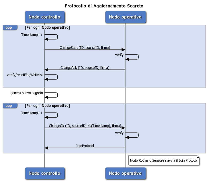
- Secret change protocol
- Periodically, the central node decides to change the secret used to sign the packet; this mechanism is useful to remove time to an attacker that want to discover the secret;
- This protocol is done by a three-way handshake, using specified frames that assure that this one has been done in a good and secure manner:
- The central node send a SECRETCHANGE_START frame in broadcast, in which it inserts its ID, a timestamp and it signs the packet with the current secret;
- The operative node receives this frame, and make some elaborations:
- it verifies if the received source ID is the same control’s source ID;
- it verifies the timestamp;
- it verifies the signature with the current secret.
- If all the checks are good, the operative node send a SECRETCHANGE_ACK in which it inserts its own ID and sign the packet with the current secret;
- The central node receive the SecretChange_Ack frame, verifying that this is the first packet of this type received by that node (to prevent against the Replay Attack), then verifies the signature, and forces to 0 the ack bit in the withelist. When it receives acks from each operative node, the central node send a SECRETCHANGE_OKframe, in which it inserts its ID, the encrypted timestamp with the symmetric key, and the same timestamp without encryption.
- The operative node receives the SecretChange_Ok frame, verifying the source ID and the timestamp, and then it starts the Join Protocol.
4 Network layer
This layer has to implement mechanisms to make realiable the communication between all the Nodes on the Network. The solution is the implementation of NLS (Network Layer Services), a framework composed by:
- a network protocol that allows the communication between the sensors, where a set of nodes communicate with the central node, and viceversa.
- a routing protocol ad-hoc DTRP (Dynamic Tree Routing Protocol), compliant with wired networks, designed to support fault tolerance, scalability and security.
- a software layer for the managment of both the protocols.
The network protocol is designed based on the following requirements:
- The communication must be bidirectional:
- from the sensors to the central node (upstream communication)
- from the central node to the sensors, in synchronous or asynchronous way (downstream communication)
- the lower layer of the stack provides an abstraction of the physical topology of the network: for each node, we find more interfaces to communicate on the network;
- The network can be unstable, with frequent failures in message exchanges; in this case, the network implements all the mechanisms to give every effort to properly route the packets, but the sending guarantee is assigned to upper layers.
- Network configuration is static: this means that a node can’t be moved in another place, or substituted. In these cases, the node is considered out of network.
- Only authenticates nodes can join to the network; a node that can’t dimonstrate its own identity can’t join.
- The computational and power resources of the nodes are strongly limited, so the communcation protocol has to minimize the packets’ number on the network and the power consumption.
4.1 Nodes’ Identity and forwarding
Each node has an unique identity on the network. A 16-bit network address assures the physical identity of the node, while at a logical level the downstream path communicates the location of the node in the logical topology.
The link between nodes are indentified by an interface address, which represent a logical abstraction of comunication channel; NLS provides 16 interfaces.
The downstream path represents a logical concatenation of all the cross interfaces to reach the central node: we can say that the NLS’ forwarding is next-hop type for upstream, and source-routing for downstream. This chooses makes less onerous computations on the nodes, delegating them to the central node.
In upstream communication, each node stores in an upstream table l’if_id (interface ID) on which forward the packet to send to the control center: it’s the main link. In the association, each node learns every possible next hop to the root, thanks to the DTRP. If the sending fails (for a failure of the channel or of the next-hop), the main link is substituted with an alternative link: the main link isn’t eliminated, but only penalized, and then it can be available another time. This mechanism protects the network from transient failure of the nodes and of the linkages.
In donwstream communication, the root node uses the downstream path learned in association phase of the nodes with itself, and stored in a downstream table that holds all the downstream paths for a specified destination. The root selects the downstream path with lower cost, and inserts it in a data downstream datagram; each node forward the datagram on the interface shown in the datagram, until the destination is reached.
4.2 Frame format
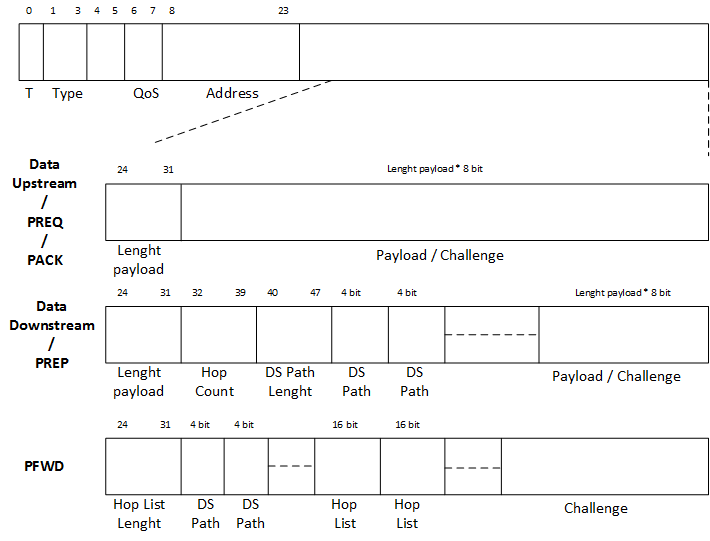
NLS defines various types of datagram; each of these have the same fields:
- T[1 bit] : identifies if the datagram contains a trailer, that is a constant field in the last bytes of the frame. The trailer can be used for authetication and integrity control;
- type[3 bits] : datagram type
- 000 : DATA UP, data to the control center;
- 001 : DATA DOWN, data to a particular node;
- 010 : PREQ, Path REQuest, control message to find a path in the network;
- 011 : PREP, Path REPlay, control message to response to a Path Request, it contains authentication info;
- 100 : PFWD, particular DATA UP, stores info about the cross node to reach the root.
- address[2 bits] : node network address
4.3 Dynamic Tree Routing Protocol
DTRP is a routing protocol ad hoc for a sensor network where a central node takes data from sensor nodes. Communication can be in upstream and downstream, without dipendence from the physical topology of the network, sensors number and technological characteristics (both wired and wireless).
Although its simple implementation, it supports security, reliability and scalability functionalities.
The protocol is divided into the following steps:
- Boot;
- Path Discovery;
- Association;
- Communication.
4.3.1 Boot
At first, the network is a quiet state, no message is exchange between the nodes.
The first node that want to communicate start the path discovery phase; theinvolved nodes wake up and start the path discovery, too.
4.3.2 Path Discovery
A node sends a request to its neighbors (all its interfaces) to find a path to the central node (PREQ packet):
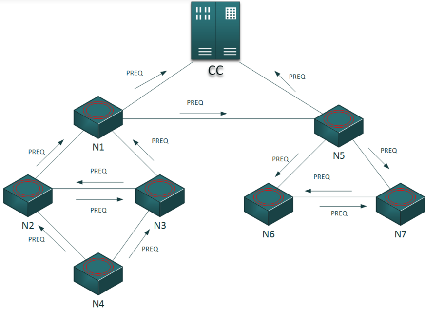
- if one of them knows a path to the central node, forward the request on its own path (PFWD packet).
- else, the neighbors enqueue the request and send themselves a path request. When one of them will know a path, it’ll forward the packet from its queue (dequeue operation).
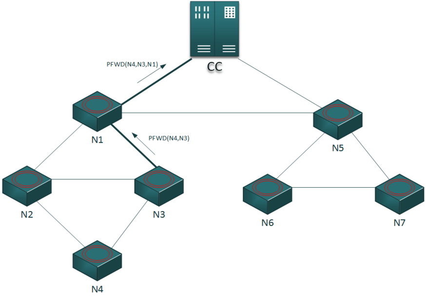
4.3.3 Association
When the central node receives a association request, and the authentication is correct, it send a response (PREP packet) to the requesting node using the path built from the intermediate nodes during the forwarding of the packet. On the PREP receiving, the node selects the interface from which it received the packet as the one to send packet to the central node. The node to which this interface is linked is the main father: so we create a tree sub-topology, with this each node can communicate with the central node cross the main father.
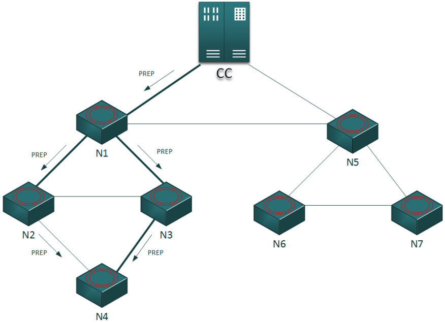
If a node receives more PREP, it stores one as main link, and the other as backup link: the nodes to which these interfaces are linked are the secondary father. This mechanism gives to the network reliability: paths in upstream or downstream are redundant.
4.3.4 Communication
An authenticated and associated node can send upstream data cross the father node. The central node can send downstream data to any associated sensor node, inserting in the packet the list of the nodes (path list) known during the path discovery. To minimize the packets’ dimension, the i-th element of the list contains the number of the interface, instead of the address.
4.4 NET APIs
NLS library contains APIs and utility functions to implement NLS protocol in software. In particular, the package net_apis contains the functions to send and receive packets from the nodes in the network, both for sensor and central node, setting in right way the file network_config.h.
5 Physical Layer
The Communication Abstraction Layer (CAL) represents the physical layer of the network and it provides a reliable communication between two nodes directly linked through eterogeneous channels.
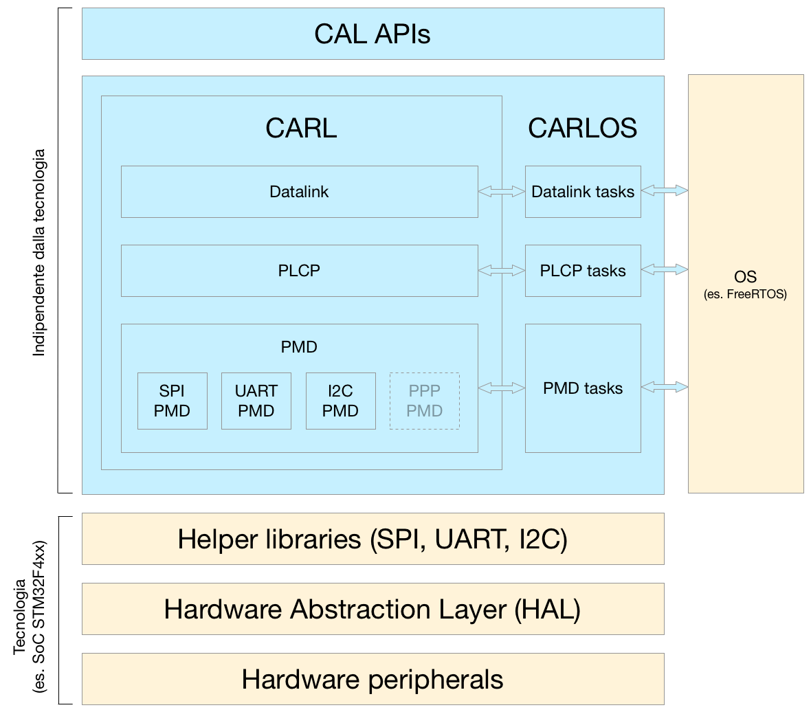
Looking to the architecture there are:
- CAL API: a set of function and callback provided to upper layers usefull to enable/disable bidirectional communication interfaces and to send/receive packets on those interfaces with different modes (unicast, broadcast,multicast)
- CArL: the module which abstracts a reliable communation of a physical and eterogeneous media through three main layers (Datalink, Physical Layer Convergence Procedure and the Physical Medium Dependant)
- CArLOS: a set of extensions which uses the CArL module and make easy the porting toward a task-oriented execution environment such as FreeRTOS
- Hardware Abstraction Layer and peripherals: software and hardware modules strictly related to technology, like SPI, UART and I2C peripherals of STM32F4xx SoC. The HELPER Library is a custom set of functions which uses the HAL in order to make even simple usage and configuration of each peripheral.
5.1 Datalink
The Datalink layer does the following actions:- Transfer and receive packets with arbitrary dimensions through frames
- Provide a reliable communication by using ACK mechanism and selective retransmissions
- Execute a CRC control on the received frames
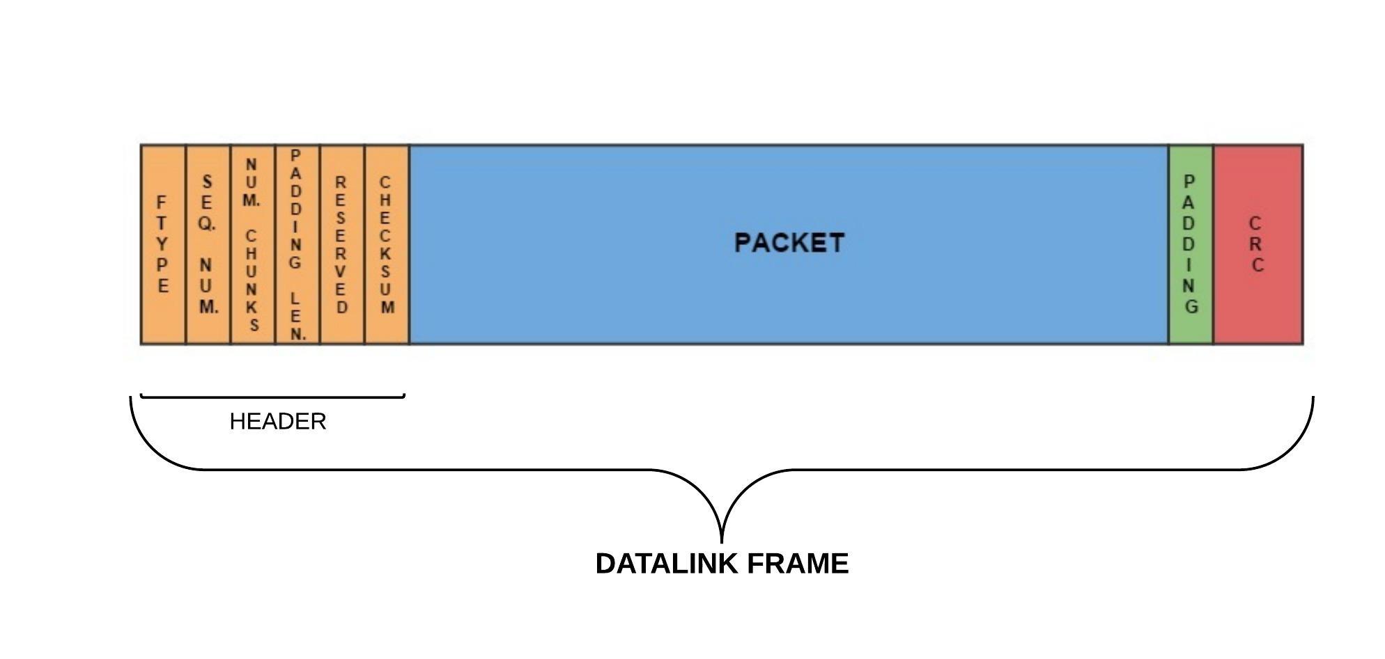
The transmission acts in this way:
- The packet to send is wrapped into the datalink frame
- The frame is pushed into TX QUEUE related to the interface logical interface IFx on which the frame must be sent.
- When the frame is going to be sent it is moved into TX STAGING AREA which stores all frames sent. This step is performed just after the previous if the interface is ready or when the PLCP calls the frameSentCallback on the interface IFx
- After the frameSentCallback the frame is moved from TX STAGING AREA to the WAITING FOR ACK STAGING AREA which collects all frame sents and waiting for acknowledgement
- The received frame in enqueued into the RX QUEUE which is periodically probed using a timer or a periodic task (see CArLOS)
- After the frame extraction there type is evaluated
- ACK: the frame acknowledged is first removed from WaitingForACK Area and than is called the proper callback (it depends on the type of the frame acknowledged)
- DATA/WELCOME: an ACK frame is sent and then the proper callback is called
- BYE: just notify that the interface has been detached
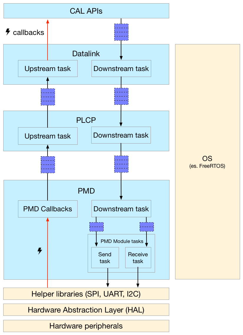
5.2 Physical Layer Convergence Procedure
The tasks of the Physical Layer Convergence Procedure (PLCP) are the following:- decompose the frame to send in fixed length units (chunk)
- recompose the chunks received during receive operation to rebuild the frame which will be moved to datalink
- configure and initialize all interfaces through the PMD layer
When peripherals are initialized they are activated to receive a chunk and, just after a chunk is received, the receipton is repetead: summarizing, each logic interface is always listening for a chunk. The receipton procedure is performed using a Finite State Machine (FSM) with two states for each interface: when it is into reset state the expected chunk should contain the frame header, while in the other state the chunk expected must have data; with this mechanism an uncorrect chunk is simply discarded and the FSM returns into reset state.
5.3 Physical Medium Dependant
The Physical Medium Dependant (PMD) is the last layer of the CArL stack and its goal is to interact with the underlying hardware and to abstract it using different communication channels to create a single logical interface: in fact a single channel could be implemented using two peripherals (e.g. I2C).The PMD layer also characterizes each CArL interface using a type attribute which represents the effective type of peripheral associated to the interface, then each PMD module is designate to use the hardware-dependant functions related to a specific type. For instance, the PMD_UART module will manage the low-level functions for all UART interfaces. The main tasks of PMD are listed here:
NEW NIKE SHOES crimson - Configuration, in which the PMD maps together the number interface and the physical peripheral and it is performed through a two mapping (logic interface -> phy interface and phy interface -> phy peripheral).
- Initialize/Deinitialize each hardware peripheral
- Send and receive data using hardware peripheral
5.4 CArLOS
CArLOS refers to CArL layer when it is joined with an Operating System (OS) in order to exploit all computational resources (e.g. in an MP-SoC architecture). With CArLOS all CArL APIs don't change because the OS uses the existing function of CArL. Actually CArLOS is supported by FreeRTOS which adopts tasks for each CArL layer and message queues instead of callbacks. There are two types of tasks: the upstream tasks manage the receive flow, while the downstream tasks manage the transmission flow. As stated above CArLOS uses the CArL function, so each task adopts the same logic but with the addition of new struments like semaphores and queues.